

What it is for
This is the density play. Same 40 ft shell as the air-cooled box, seven times the compute, because the heat leaves through a pipe instead of a fan. Two racks of seven layers, fifteen units per layer, a 150 m³/h glycol loop and a dry cooler outside.
It is not a cheaper box — it is a smaller site. At 1.2 MW per container, a 10 MW farm needs nine boxes instead of fifty-six, and the fencing, the cabling and the land all shrink with it.
Where it is typically used
Key specifications
| Shell | 40HC, CSC plated, 12,192 × 2,438 × 2,896 mm |
| Units | 210 × S21 hydro, 2 racks × 7 layers × 15 |
| Design load | 1.2 MW at 35 °C ambient |
| Loop | 40% glycol, 150 m³/h, DN57 304 stainless |
| CDU | Single pump, 150 m³/h, plate exchanger |
| Heat rejection | Dry cooler 1,306.8 kW, 1,741 m² coil, 8 × 910 mm fans |
| Fan power | 33.2 kW total, 240,000 m³/h |
| Noise | 57 dB(A) at 10 m |
| Power | 2 × 1,250 A, 105 × 20 A per cabinet |
| Build time | 35–50 days from drawing release |
Figures are for the standard configuration and change with the project. Values are design values; acceptance follows the contract technical agreement.
What goes in the box
Installed, wired and tested before dispatch. On site the work is placement and external connections.
Two seven-layer hydro racks with 28-way manifold, fifteen outlets per side.
150 m³/h pump, plate exchanger, strainer, bypass and fill point.
DN57 304 stainless, insulated, pressure-tested at 1.5× before shipping.
Shipped with the box; site piping and the pad are site work.
PLC interlinking CDU and cooler fans; pump seal, hoses, glycol kit.
Which model to take
| Model | Units | Load | Cooler | Ambient |
|---|---|---|---|---|
| MC-WAT-40-S | 210 | 1.2 MW | 1,306 kW | 35 °C |
| MC-WAT-40-H | 210 | 1.2 MW | 1,500 kW | 45 °C |
| MC-WAT-40-C | 196 | 1.12 MW | 1,306 kW | −30 °C |
Standard models are listed. Other capacities are built to order, with two to three weeks added to the standard lead time.
The 8.9% margin on the dry cooler is the whole design
Sizing at the load is how loops derate
The cooler is rated 1,306.8 kW against a 1,200 kW design load. That 8.9% covers a dirty coil, a hot week and a glycol mix that is richer than ideal. Size it at 1,200 kW and the loop runs at 45 °C instead of 40, the machines throttle, and the farm makes less than its nameplate for the hottest six weeks of the year.
The trade is fan power: eight 910 mm fans moving 240,000 m³/h cost 33.2 kW, which is 2.8% of the load. That is the cheapest insurance in the box.
When to use it, when not to
These come from projects rather than general advice. Match your case against them; it is more useful than reading the specification table.
Water is the only route at this density.
Plan the pad, the pipe run and the cleaning access before you order.
A pump seal and a quarterly test are not optional, and a failed loop cooks 210 machines.
Several tonnes of glycol have to reach the site once, and again after any major repair.
From contract to energisation
Unit model, ambient, wet-bulb, altitude, cooler position. 7 days.
35–50 days, loop tested before dispatch.
Pressure test at 1.5×, then 72 hours at design load with the ambient logged.
Container and cooler on one bill; site piping by others.
On site and in detail
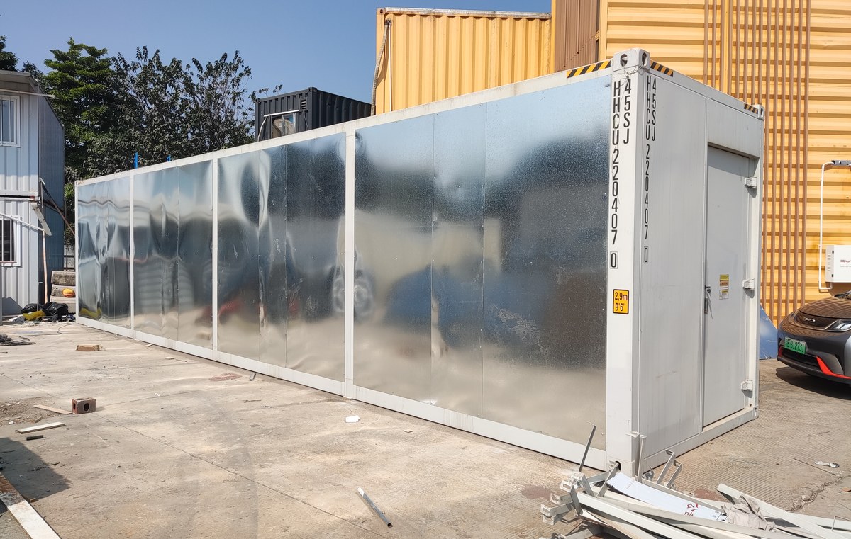
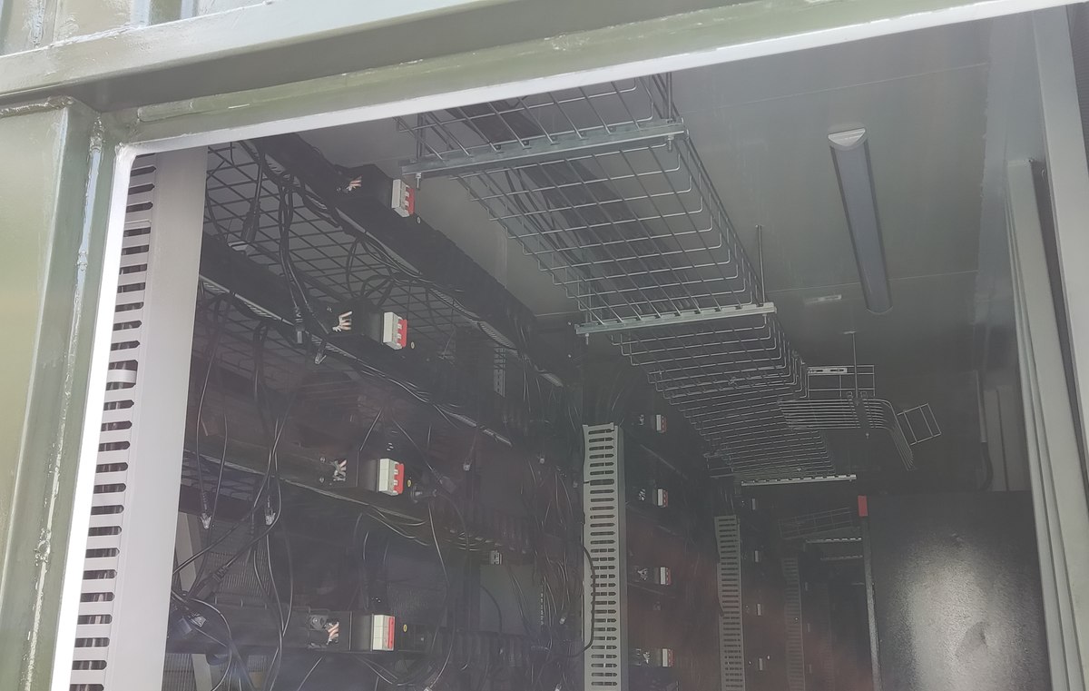
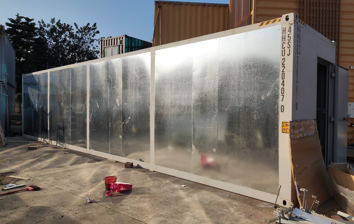
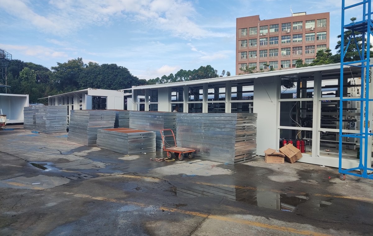
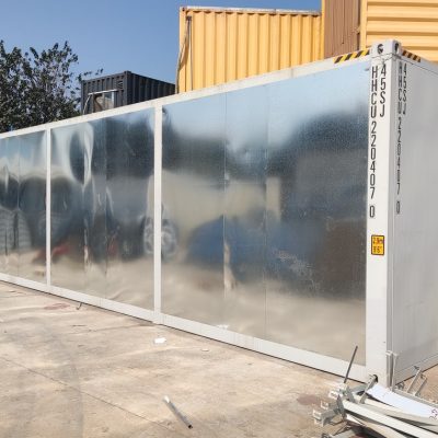
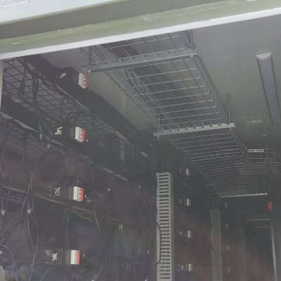
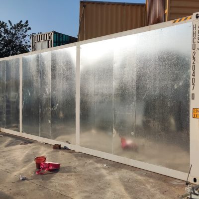
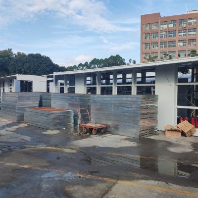
Some images are scheme illustrations and renders showing structure and layout. Final delivery follows the contract drawings.
What customers ask most
Can I use my own dry cooler?
Yes, if it is rated for the flow and the approach. Send the curve; we will check it against the loop before we ship.
What if the pump fails?
The PLC drops the load on the affected rack and alarms. A standby pump is an option and is worth taking on unmanned sites.
How long does commissioning take?
Three to four days: flush, fill, leak test, then a 72-hour run at design load.
Is 1.2 MW achievable at 45 °C ambient?
Yes, with the larger cooler. The box does not change; the rejection side does.
Ask for a scheme for your site
Send the capacity, rack count, site conditions and local climate. You get a layout, a single-line diagram and a price, at no charge, revised until it works.