

What it is for
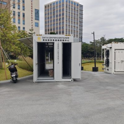
A 20 ft water-cooled box is what you buy when the site is small, the power is cheap and air cooling would need a box twice the size. Ninety-six hydro units on two racks, a 60 m³/h loop and a CDU that fits behind the door.
It is also the box for a site where the trailer cannot be longer than six metres: the loop and the machine count scale down together, so nothing here is a compromise on the cooling principle, only on the volume.
Where it is typically used
Key specifications
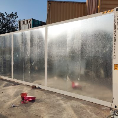
| Shell | 20GP, CSC plated, 6,058 × 2,438 × 2,591 mm |
| Units | 96 × S21 hydro, 2 racks × 4 layers × 12 |
| Design load | 0.55 MW |
| Loop | 40% glycol, 60 m³/h, DN32 304 stainless |
| CDU | Single pump, plate heat exchanger, 600 kW rejection |
| Power | 1 × 800 A main, 48 × 20 A branch |
| Noise | 55 dB(A) at 10 m |
| Build time | 30–40 days from drawing release |
Figures are for the standard configuration and change with the project. Values are design values; acceptance follows the contract technical agreement.
What goes in the box
Installed, wired and tested before dispatch. On site the work is placement and external connections.
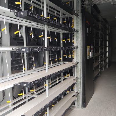
Certified 20GP with two four-layer hydro racks and manifold at the rear.
Pump, plate exchanger, strainer and bypass, accessible from the door.
Twelve outlets per rack side, drip tray under each layer.
Loop temperature and differential pressure to your SCADA, dry contacts.
Pump seal, hose set, one manifold outlet and a glycol test kit.
Which model to take
| Model | Units | Load | Loop | Cooler |
|---|---|---|---|---|
| MC-WAT-20-S | 96 | 0.55 MW | 60 m³/h | 1 × 600 kW |
| MC-WAT-20-L | 84 | 0.48 MW | 60 m³/h | 1 × 500 kW |
| MC-WAT-20-P | 96 | 0.55 MW | 60 m³/h | Shared 1.3 MW bank |
Standard models are listed. Other capacities are built to order, with two to three weeks added to the standard lead time.
Sharing one dry cooler between boxes saves more than it costs
A shared bank is normal practice below 2 MW
Two 20 ft boxes and one 1.3 MW dry cooler cost less than two dedicated coolers, occupy less pad, and give you N+1 on the fans. The price is that the loop has to be balanced and the PLC has to know which box is which.
We size shared banks at 1.1× the sum of the boxes rather than 1.3× each, because they rarely peak together and the diversity is real.
When to use it, when not to
These come from projects rather than general advice. Match your case against them; it is more useful than reading the specification table.
This is the only configuration that fits.
Buy the shared cooler now; retrofitting a bank costs more than upsizing it.
A water loop needs a quarterly check. Without it, air is honest.
At 40% glycol the loop gels. Go to 50% and tell us the winter minimum.
From contract to energisation
Unit model, ambient range, cooler location. Five days.
30–40 days, loop pressure-tested before shipping.
Loop at 1.5× working pressure, then 24 hours on load.
Two per 40HQ; manifolds braced, glycol shipped separately.
On site and in detail
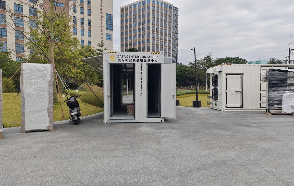
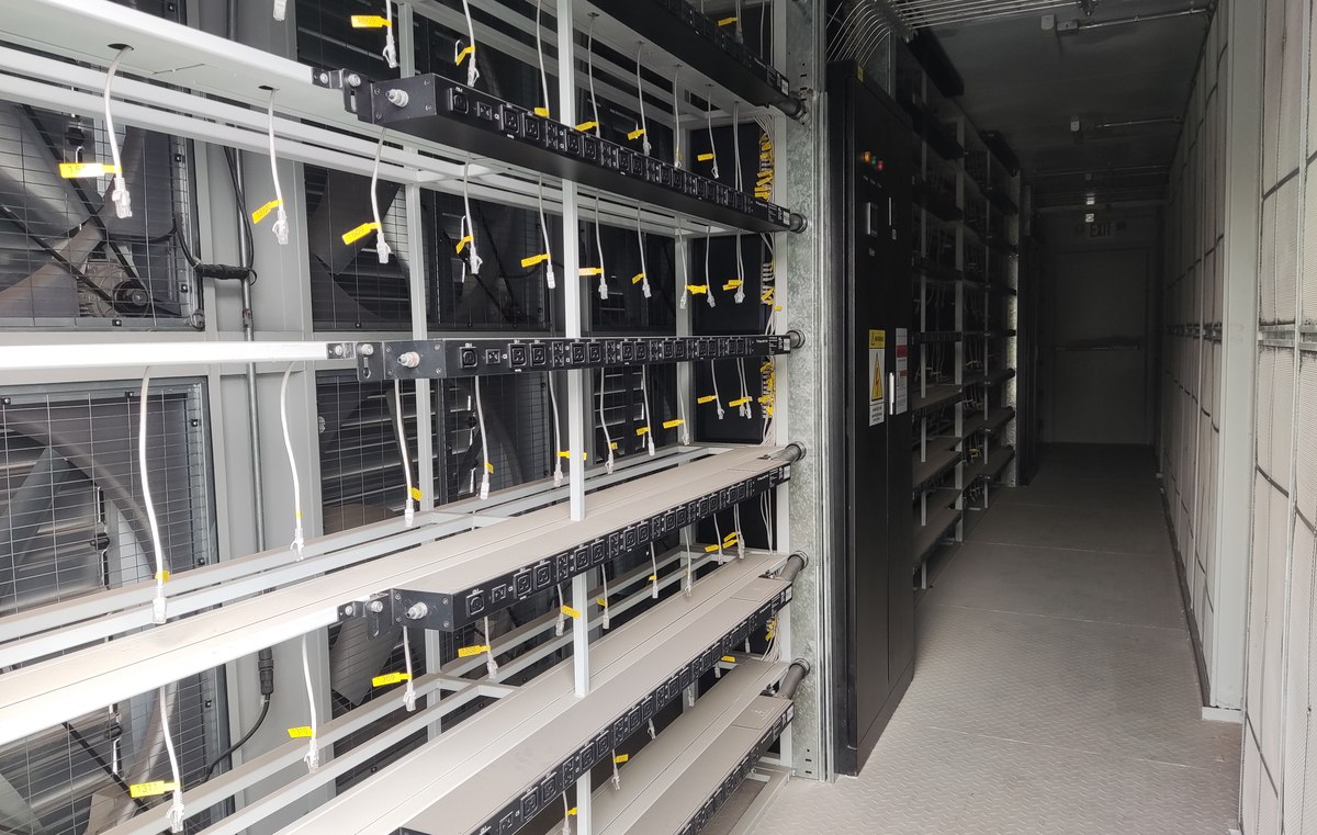
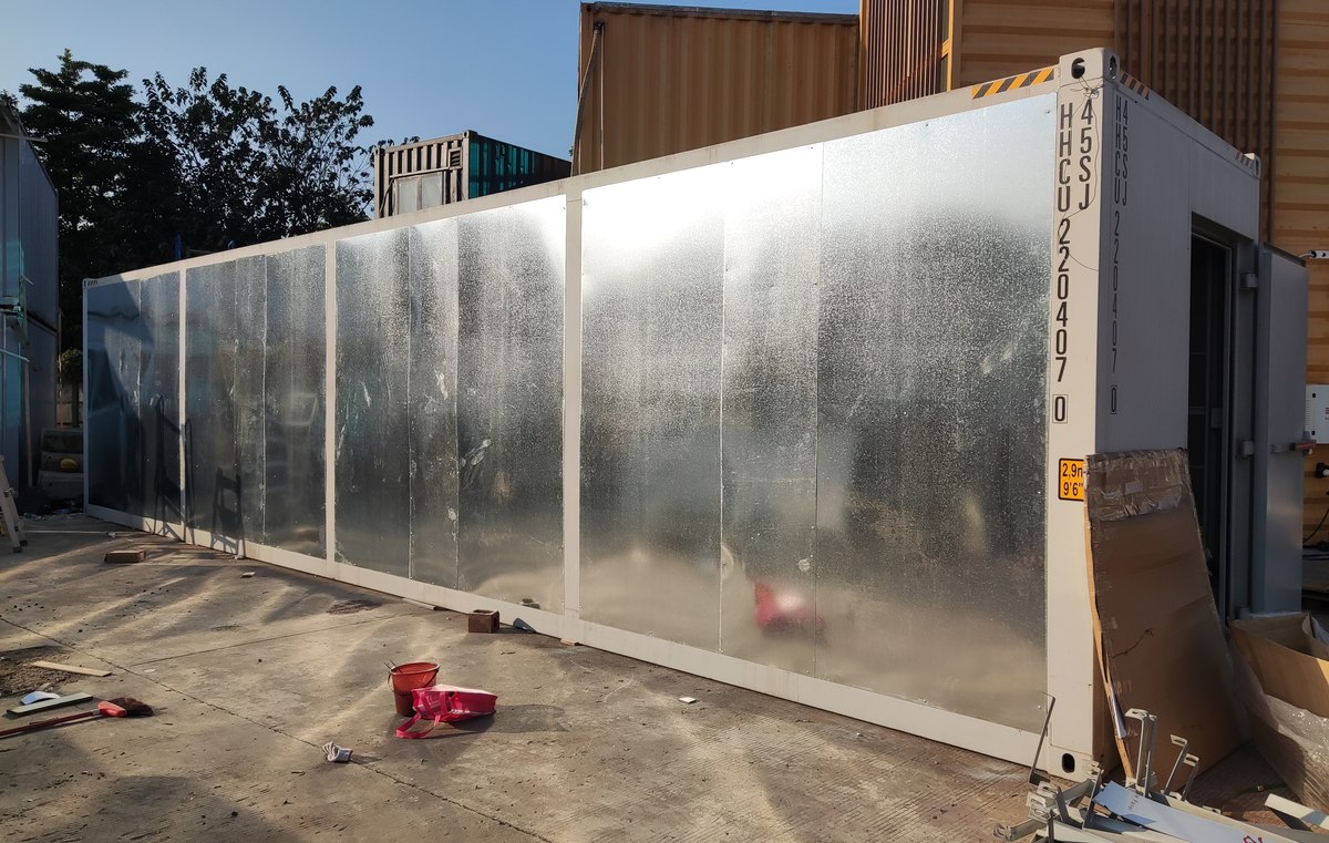
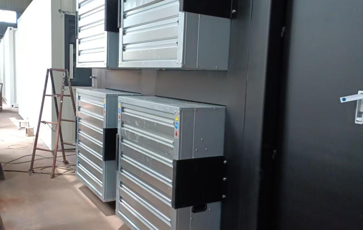
Some images are scheme illustrations and renders showing structure and layout. Final delivery follows the contract drawings.
What customers ask most
Can the cooler be on the roof of the box?
At 600 kW, yes on some builds, but the structure needs reinforcing and access for cleaning is poor. Grade level is better.
How much glycol per box?
About 0.9 m³ including the loop to the cooler.
Does it need a water supply?
No. It is a closed glycol loop with a dry cooler; water is only needed for the initial fill.
Ask for a scheme for your site
Send the capacity, rack count, site conditions and local climate. You get a layout, a single-line diagram and a price, at no charge, revised until it works.