

What it is for
Water-cooled farms exist because air cannot get the heat out at the density the machines now run at. The trade is that the heat rejection moves outside the box and becomes a site system: a loop, a pump set, a dry cooler bank and a water or glycol inventory that somebody has to maintain.
We build that as one package — hydro containers, shared dry cooler bank, primary/secondary pumping and the control that keeps the two in step. The reason to do it as one package is simple: a container that expects 150 m³/h and a cooler bank that delivers 120 m³/h will both run, and both will be wrong.
Where this stops making sense is where water is scarce or the winter is hard. A dry cooler handles both, a wet cooling tower does not, and an adiabatic unit sits in between with a water bill attached.
Where it is typically used
Key specifications
| Site capacity | 2–10 MW, 1.2 MW per 40 ft container |
| Containers | 210 × S21 hydro per box, 2 racks × 7 layers × 15 |
| Loop | 40% ethylene glycol, 150 m³/h per box, DN57 304 stainless |
| Heat rejection | Shared dry cooler bank, 1,306.8 kW per box of capacity |
| Approach | 8–10 °C above ambient at design wet-bulb |
| Pumping | Primary variable speed, secondary constant, N+1 |
| Make-up | Glycol top-up point per loop, 200 L expansion vessel |
| Noise | 57 dB(A) at 10 m for the container, 62 for the cooler bank |
| Footprint | About 380 m² for 10 MW including the cooler bank |
| Build time | 35–50 days per box, 10–14 weeks to energise |
| Control | PLC interlinking CDU, pumps and cooler fans |
| Standard | CSC shell, PED-ready pressure parts on request |
Figures are for the standard configuration and change with the project. Values are design values; acceptance follows the contract technical agreement.
What goes in the box
Installed, wired and tested before dispatch. On site the work is placement and external connections.
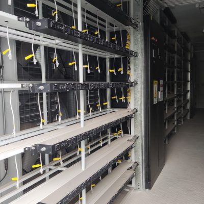
210 S21 hydro units each, manifolded at fifteen outlets per rack side.
Finned coil, axial fans, sized on your wet-bulb and altitude rather than a catalogue.
Primary/secondary with strainers, bypass and a fill point that a site technician can reach.
Pre-fabricated spools to the cooler bank, insulated, pressure-tested before shipping.
One PLC per farm, dry contacts to your SCADA, alarm on differential pressure and tank level.
Flush, fill, leak test at 1.5× working pressure, then 72 hours under load.
Which model to take
| Stage | Containers | Load | Cooler bank | Footprint |
|---|---|---|---|---|
| Stage 1 | 3 | 3.6 MW | 4 × 1.3 MW | ≈ 150 m² |
| Stage 2 | 5 | 6.0 MW | 6 × 1.3 MW | ≈ 220 m² |
| Stage 3 | 8 | 9.6 MW | 9 × 1.3 MW | ≈ 330 m² |
| Stage 4 | 10 | 12 MW | 12 × 1.3 MW | ≈ 380 m² |
Standard models are listed. Other capacities are built to order, with two to three weeks added to the standard lead time.
The number that decides a water-cooled farm is the approach temperature
Dry cooler sizing is not a catalogue pick
A dry cooler rated at 1,306.8 kW against a 1,200 kW load is not 8.9% generosity for its own sake. It is what you need when the ambient hits its design maximum and the coil has been through a summer of dust. Size it at the load and the loop runs at 45 °C instead of 40, the machines throttle, and the farm produces less than the nameplate.
Altitude matters as much as ambient. At 2,000 m the air is thin enough that the same fan moves about 20% less mass, and the coil has to grow to compensate.
Glycol concentration is a freeze decision
40% ethylene glycol protects to about −24 °C. If your site sees −35 °C you need 50%, and the same loop then carries about 8% less heat per litre, which goes back into the cooler sizing. It is cheaper to tell us the winter minimum than to discover it in January.
When to use it, when not to
These come from projects rather than general advice. Match your case against them; it is more useful than reading the specification table.
This is the case water cooling was invented for.
The container runs at 57 dB(A); the cooler bank is the louder of the two and can be placed away from the fence.
Dry cooling handles frost without a water inventory if the concentration is right.
A pump seal, a strainer and a glycol test every quarter are not optional. Without them, air cooling is the honest answer.
A 10 MW farm holds several tonnes of fluid. If a truck cannot reach the site, rethink.
From contract to energisation
Ambient max/min, wet-bulb, altitude, water quality, noise limit at the fence.
Loop diagram, cooler layout and stage plan in 7–10 working days.
Drawing release; coolers and containers ordered in parallel.
35–50 days per container, cooler bank 45–60 days.
Flush, fill, pressure test, then 72 hours at design load with the ambient logged.
On site and in detail
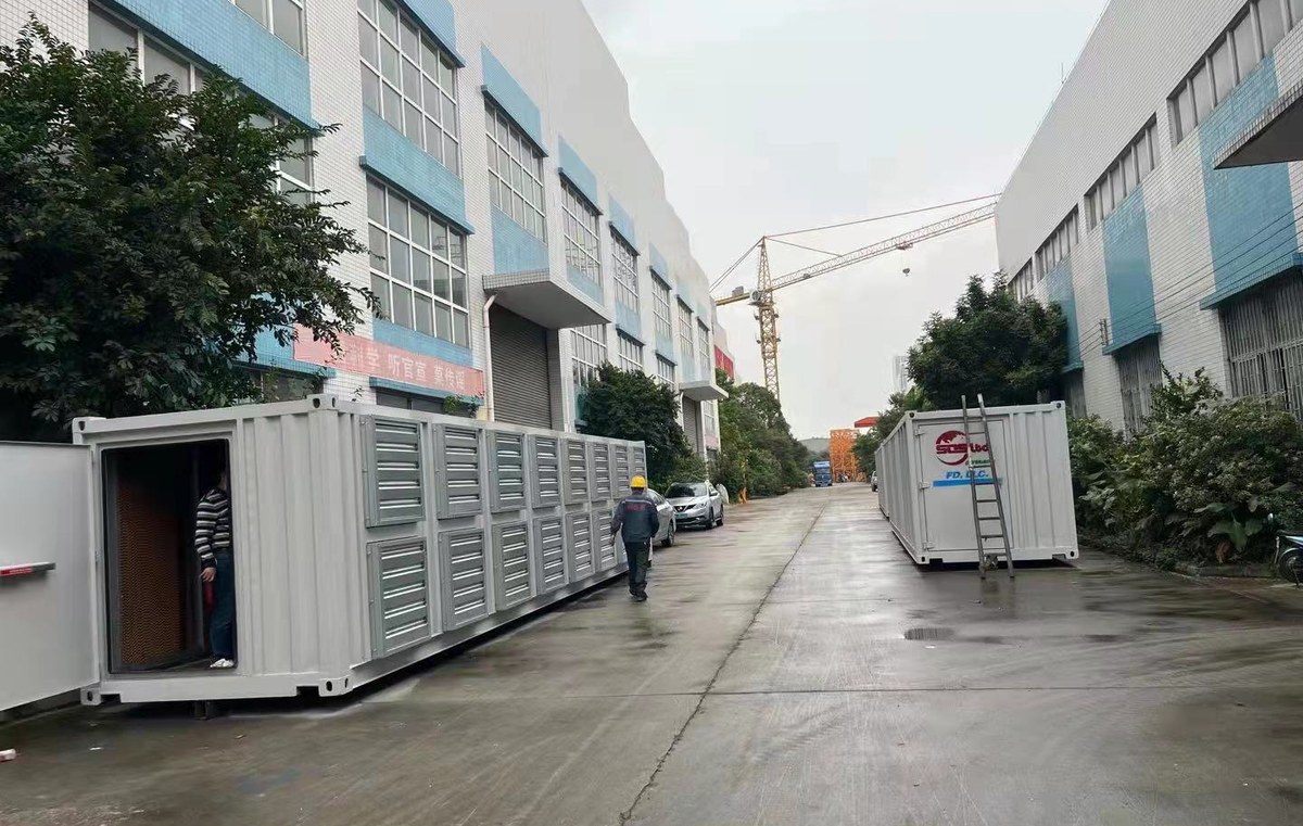
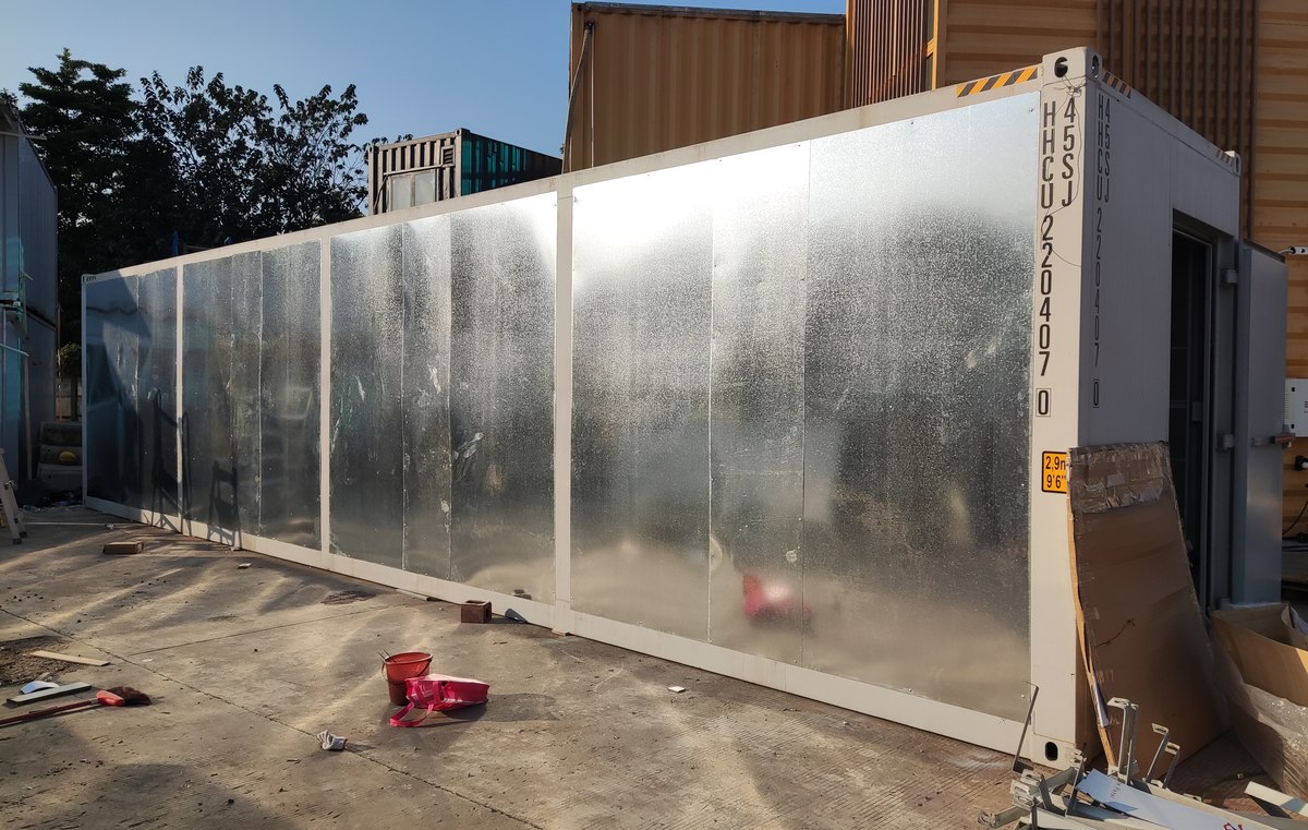
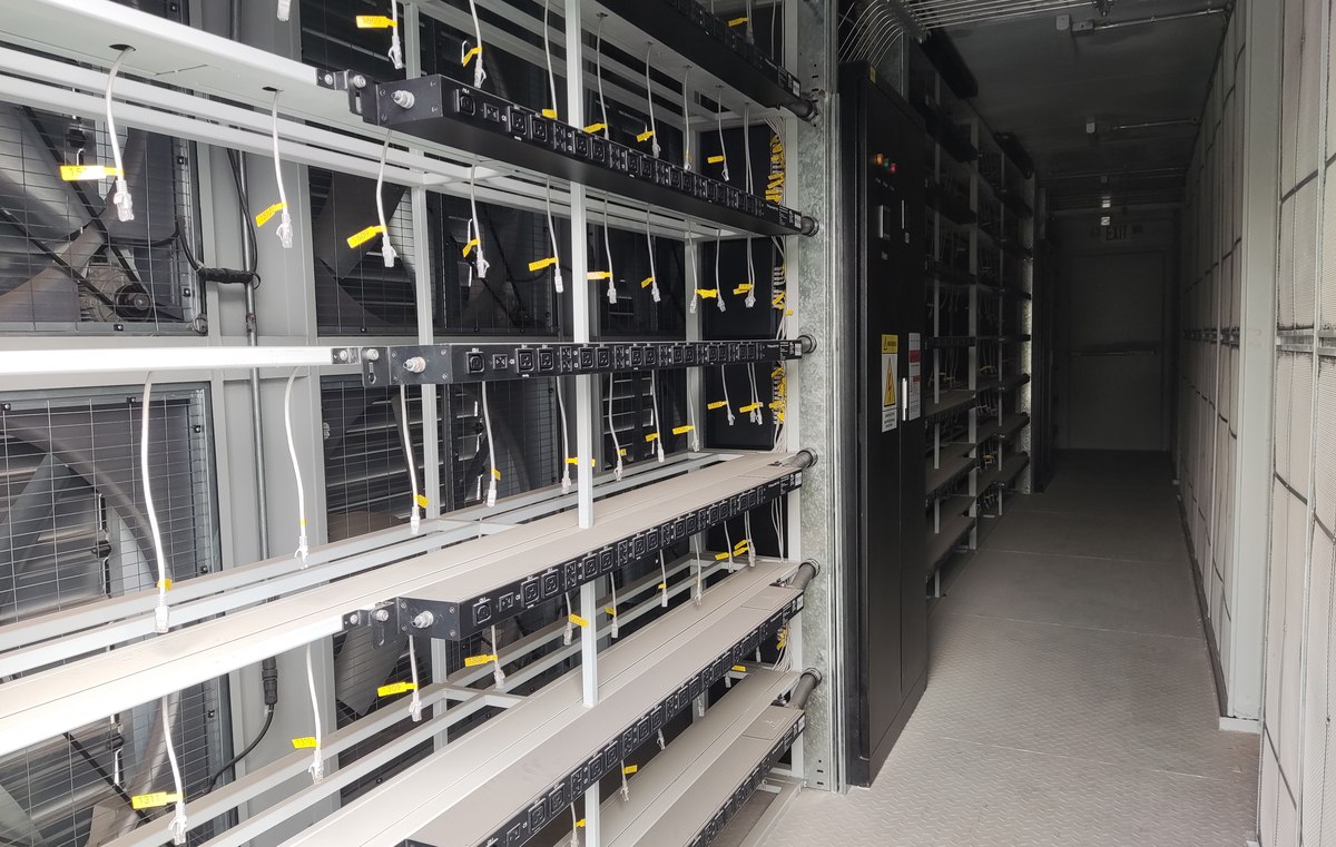
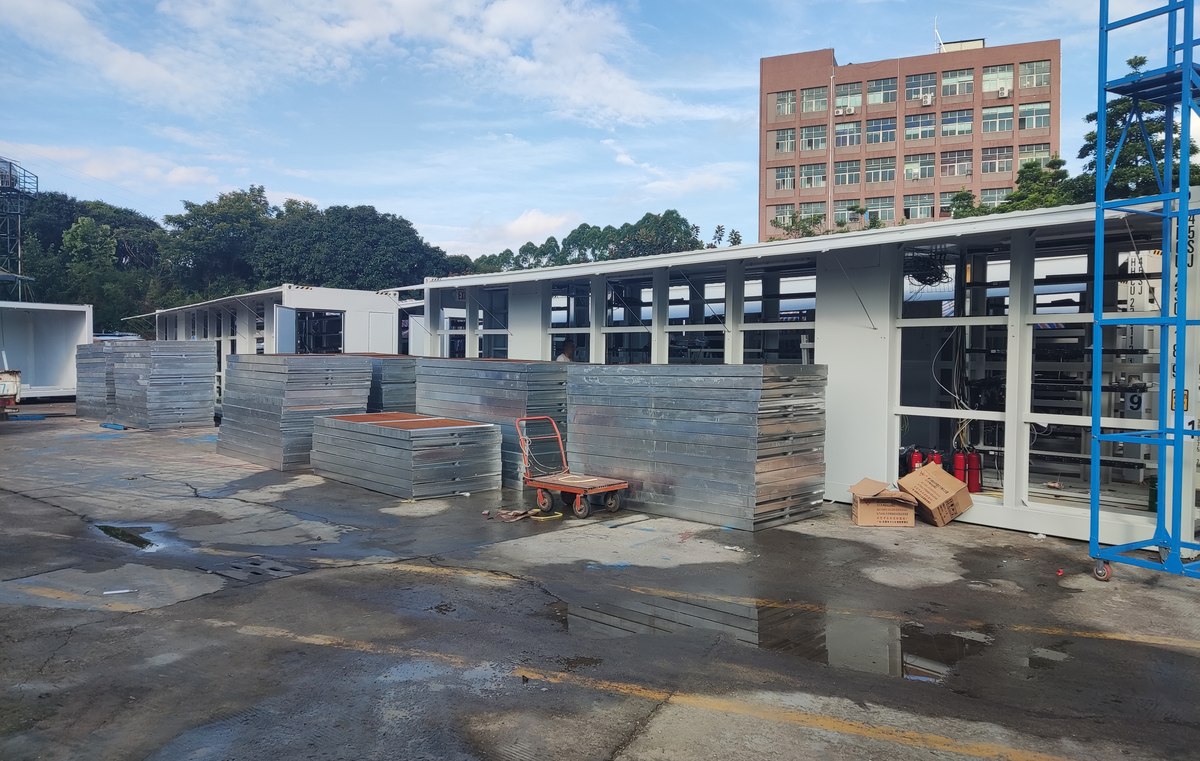
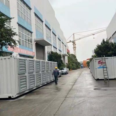
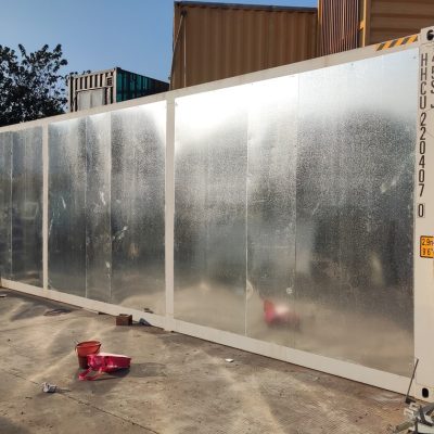
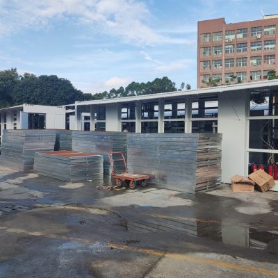
Some images are scheme illustrations and renders showing structure and layout. Final delivery follows the contract drawings.
What customers ask most
Can the dry cooler sit on the container roof?
On a 20 ft box, sometimes. On a 40 ft at 1.3 MW, the coil area will not fit and the structure will not carry it. Plan a grade-level bank.
What if we already have a cooling tower?
We can tie into it, but a tower delivers colder water than the loop needs and brings water treatment with it. Send the tower curve and we will tell you whether it is worth it.
How much glycol does a 10 MW farm need?
Roughly 1.8 m³ per container plus the cooler bank and pipework — around 22 m³ at 10 MW. Budget for a delivery and a spill kit.
Is 57 dB(A) measured or calculated?
Measured on a supplied unit at ten metres, free field. The cooler bank is calculated and we will not quote a number we have not tested.
What happens on a pump failure?
N+1 pumping with automatic changeover, and the PLC drops the load on the affected loop rather than letting it overheat.
Ask for a scheme for your site
Send the capacity, rack count, site conditions and local climate. You get a layout, a single-line diagram and a price, at no charge, revised until it works.