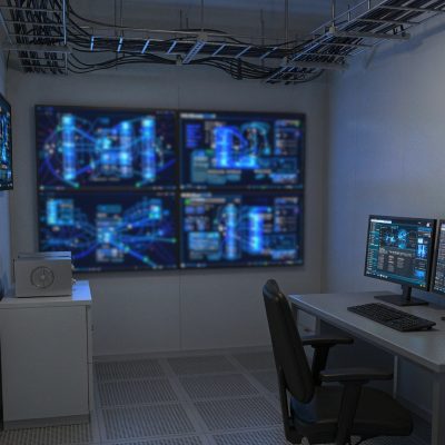


What it is for
A 6 MW hall built the conventional way runs about 20 months from piling to first load, and 9–12 of those months are M&E installation. Very little of that time is spent installing equipment. Most of it is spent waiting: for the roof, for concrete to reach strength, for a cleanliness test to pass before anything can be wheeled in. The trades are hard-sequenced, so the programme will not compress.
We put the M&E into the containers instead. IT, power, battery and cooling each become a module, assembled, wired, pressure-tested and load-tested in the factory and run once at full load before it ships. On site three things remain: pour the foundation, lift the modules into place, connect utility power and fibre.
On a 6 MW project we have gone from steel cutting to energisation in 16 weeks. That assumes the foundation and the utility connection arrive as drawn. Both sit outside our scope, and both are where site programmes usually slip, so contracts are split by milestone with each party owning its own dates.
Expansion works the same way. Adding 2 MW in a second phase does not mean reopening a building site. It means another row of modules, one more busbar run and one synchronisation, and it can be carrying load within two weeks.
Where it is typically used
Key specifications
| Total IT capacity | 2 / 6 / 12 / 20 MW, buildable in four phases |
| IT power per module | 250 / 350 / 500 kW |
| Racks per module | 6 / 7 / 9 (600 × 1200 × 2000 mm standard) |
| Design power per rack | 8–25 kW air-cooled, 30–60 kW liquid-cooled |
| Power architecture | N+1 as standard, 2N to Tier IV on request |
| UPS | Modular 400 / 600 / 800 kVA, 96% double-conversion, 99% ECO |
| Battery autonomy | 10 / 15 / 30 minutes, lithium iron phosphate |
| Cooling | Indirect evaporative / chilled water with dry coolers / cold plate |
| Design PUE | 1.18 in dry climates to 1.28 in hot-humid climates |
| Enclosure protection | IP54, IP55 optional |
| Fire | 60-minute enclosure rating, clean-agent suppression inside |
| Seismic | To site requirements, up to intensity 8 |
| Ambient temperature | −25 °C to +50 °C |
| Structural design life | 25 years |
Figures are for the standard configuration and change with the project. Values are design values; acceptance follows the contract technical agreement.
What goes in the box
Installed, wired and tested before dispatch. On site the work is placement and external connections.
40 ft enclosures, 6–9 racks, sealed cold aisle, dual PDU per rack, power and fibre trays run separately.
UPS, LV distribution, ATS and rack PDUs in one enclosure, cables entering through a floor trench.
LFP racks, BMS, independent clean-agent suppression. Physically separated from IT so a thermal event stays inside.
Indirect evaporative or chilled-water units selected against local climate, pipework insulated inside the enclosure.
N+1 gensets, day tanks and synchronising panels, in their own fenced compound away from the IT area.
Agent cylinders, pre-action valves and the alarm panel, sized to cover the whole module array.
Environmental monitoring, access control, CCTV and out-of-band management on a separate network.
Service walkways, cable trays, chilled-water and fire pipework between modules, all bolted on site.
Which model to take
| Model | Total capacity | Racks | Modules | Power architecture | Cooling |
|---|---|---|---|---|---|
| CAMPUS-2 | 2 MW | 40 | 8 | N+1 | IDEC / chilled water |
| CAMPUS-6 | 6 MW | 120 | 24 | N+1 / 2N | IDEC / chilled water |
| CAMPUS-12 | 12 MW | 240 | 48 | 2N | Chilled water / liquid |
| CAMPUS-20 | 20 MW | 400 | 80 | 2N | Chilled water / liquid |
Standard models are listed. Other capacities are built to order, with two to three weeks added to the standard lead time.
Tier levels and PUE: the two things most often glossed over
Tier III and Tier IV are not a small step apart
Tier III is concurrent maintainability: any single piece of equipment can be taken out for service while the load keeps running. That means N+1 redundancy plus a path you can transfer load onto. It permits a single fault to drop the load. It only forbids planned work from doing so.
Tier IV is fault tolerance: any single failure, including an unplanned one, leaves the load unaffected. That requires 2N or 2(N+1), two physically separate power paths, and separate cable routes down to tray level.
The cost gap is real. Going from Tier III to Tier IV roughly doubles the electrical plant, adds floor area, and typically lifts total investment by 35%–50%. Plenty of tender documents say Tier IV and get built to Tier III, with the gap papered over at commissioning by compensatory measures. It is an open secret in the industry, but an owner who runs the numbers will find it eventually.
Chinese A / B / C grades do not convert into Tiers
GB 50174 grades data centres A, B and C by the loss an outage would cause. Grade A demands fault tolerance and lines up broadly with Tier IV. Grade B demands redundancy, close to Tier III. Grade C roughly matches Tier I or II.
But the two standards check different things and cannot be mapped one to one. If a tender asks for both Tier III and Grade A, establish which standard will be used for acceptance and who issues the certificate. We have seen projects specified against Uptime’s design documents, and projects that only needed a third-party statement of conformity.
PUE is calculated, not quoted
PUE is annual site energy divided by IT energy. Site energy includes cooling, distribution losses, lighting, fire and monitoring, and the boundary you draw changes the number substantially.
It is also strongly climate-dependent. The same indirect evaporative design reaches 1.18 in Hohhot, where both dry-bulb and wet-bulb stay low, and only 1.35 in Shenzhen. Any figure we quote is calculated from ten years of weather data at the project site. A generic 1.2 means nothing.
The boundary has to be stated as well. Ours follows GB/T 51314: cooling, distribution and lighting included; office and domestic loads excluded; generator block heaters excluded. Some quotations drop office load from the boundary, which flatters the number but is not honest.
When to use it, when not to
These come from projects rather than general advice. Match your case against them; it is more useful than reading the specification table.
A campus beats civil construction by ten months or more, and that time is usually the customer’s market window.
Do not use campus scale. The fixed cost of generators, fire suppression, monitoring and foundations cannot be spread thin enough. A cluster or a twin-module pair is cheaper.
Do not choose indirect evaporative cooling. Water demand is high and the media scale quickly, so maintenance eats the electricity saved. Move to chilled water with dry coolers.
Reserve foundation pads and busbar interfaces. Phase two adds modules and leaves the primary side alone.
From contract to energisation
Capacity, power per rack, cooling type, certification and local code. Vagueness here turns into variations later.
Single-line diagram, layout, structural loads, fire strategy and interface schedule, issued to the owner and the civils contractor.
Enclosures, assembly, wiring, pressure testing and load testing. The owner may witness; test records ship with the modules.
Abnormal-load permits by module size; a 50–100 t mobile crane sets three to four modules a day.
Connection checks, insulation tests, individual commissioning, load transfer and synchronisation, then the SAT report.
On site and in detail
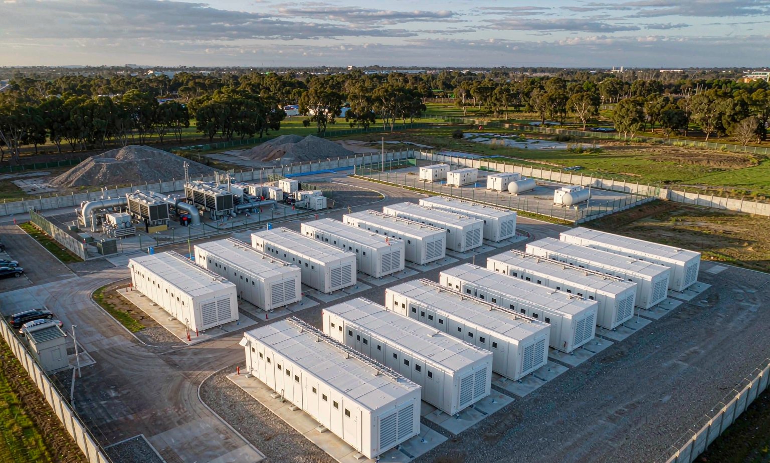
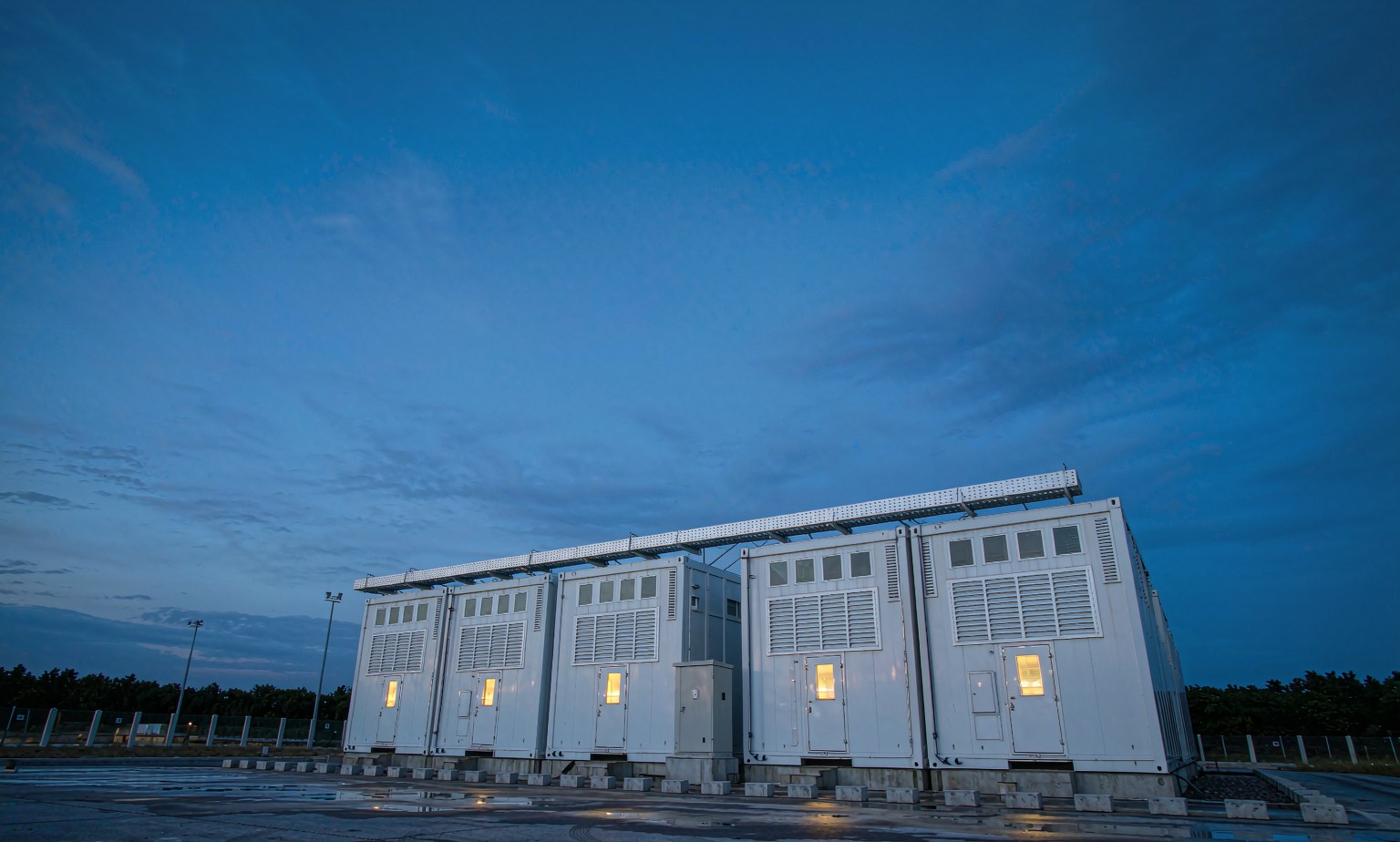
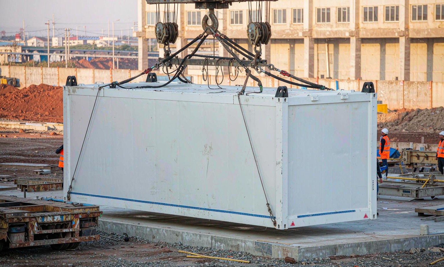
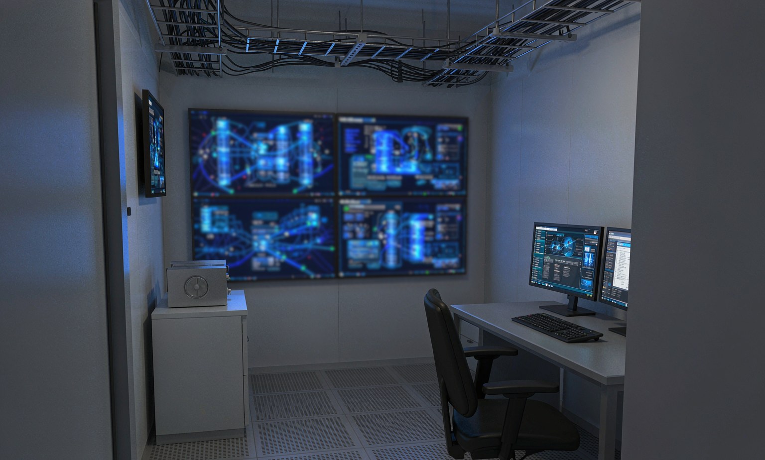
Some images are scheme illustrations and renders showing structure and layout. Final delivery follows the contract drawings.
What customers ask most
How much civil work is needed on site?
Levelling, isolated or raft foundations, cable trenches, the utility connection, water and drainage interfaces, and fencing. For 6 MW the civil package runs about 6–8 weeks and can run in parallel with factory build, so it is off the critical path.
Can it go on a roof?
Yes, but check the imposed load. A fully loaded 40 ft IT module weighs about 22–28 t, which over 28 m² is 8–10 kN/m². Most office slabs cannot take that and need a steel platform to spread the load.
How are modules connected?
Power by prefabricated busbar or cable tray, chilled water by insulated pre-fabricated pipe, fire pipe and fibre through the service links. Everything is bolted. No hot work, no welding on site.
Does it work in extreme cold and heat?
Enclosures are configured for −25 °C and +50 °C. Extreme cold needs trace heating and antifreeze; extreme heat needs more condenser area and a derated rating. Both are options and both have to be stated in the quotation.
What certification is available?
CE, UL and TÜV to order. Structure can be verified to IBC or Eurocode. Chinese projects follow GB 50174 and local fire requirements.
When does the delivery period start?
At drawing approval and receipt of the deposit, not at signature. Design changes extend it, and the extension mechanism belongs in the contract.
Ask for a scheme for your site
Send the capacity, rack count, site conditions and local climate. You get a layout, a single-line diagram and a price, at no charge, revised until it works.