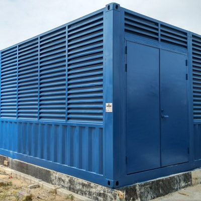


What it is for
A water treatment plant in a container is a process skid with a roof. What makes it work is not the membrane or the dosing pump — it is the floor that slopes to a drain, the pipe penetrations that were cut before the lining went in, and the fact that somebody piped it in a factory instead of on a wet site.
We build the room and the process skid inside it: filtration, dosing, pumps, controls, drainage and the frost protection the site needs. The process design is agreed with you or your water engineer, and we do not pretend to be the process designer.
Where these units go is where a plant room cannot: mining camps, construction villages, resorts on an island, and factories that need to prove pre-treatment before discharge. In all four cases the container is the reason the project is possible, not a cost saving.
Where it is typically used
Key specifications
| Shell | 10 / 20 / 40 ft, or a 40 ft high cube for tall skids |
| Flow range | 5–50 m³/h depending on process, stated per project |
| Process | Sand or multimedia filtration, carbon, softening, RO, UV or dosing as required |
| Dosing | Chemical dosing skid with duty and standby pumps, bunded chemical store |
| Pump set | Duty and standby, 2–15 kW, with dry-run protection |
| Floor | Sloped to a drain, epoxy-coated, bunded where chemicals are stored |
| Penetrations | Welded pipe sleeves, spare ways capped, all cut before lining |
| Drainage | Internal gully to a site connection, with a sample point |
| Frost protection | Trace heating and insulation for cold sites; ventilation for hot ones |
| Controls | PLC with HMI, dosing proportional to flow, alarm contacts to the site system |
| Corrosion | C4 standard; stainless wetted parts where the water demands it |
| Design ambient | −30 °C to +50 °C, stated in the contract |
Figures are for the standard configuration and change with the project. Values are design values; acceptance follows the contract technical agreement.
What goes in the box
Installed, wired and tested before dispatch. On site the work is placement and external connections.
Filtration vessels, membranes or dosing tanks on a frame that was piped and pressure-tested in the yard.
Duty and standby pumps with dry-run protection, isolation valves and a drain.
Bunded compartment, separate ventilation, signage and a spill kit.
Sloped epoxy floor, gully, sample point and a discharge connection.
Welded sleeves and pre-fabricated pipe spools so site work is connection, not fabrication.
PLC and HMI, dosing proportional to flow, remote alarm contacts.
Which model to take
| Model | Shell | Flow | Process | Use |
|---|---|---|---|---|
| EQ-WT-10 | 10 ft · 2,991 mm | 5–10 m³/h | Filtration + UV | Small camp, single borehole |
| EQ-WT-20 | 20 ft · 6,058 mm | 10–25 m³/h | Filtration + carbon + dosing | Camp, resort |
| EQ-WT-40 | 40 ft · 12,192 mm | 25–50 m³/h | Multimedia + RO + dosing | Industrial, mining |
| EQ-WT-40D | 40 ft · two rooms | 25–50 m³/h | Process + chemical store | Where chemicals must be separated |
Standard models are listed. Other capacities are built to order, with two to three weeks added to the standard lead time.
The floor slope and the pipe sleeves are decided before the lining goes in
Cut once, in the right place
A container is a finished, painted, insulated object. Every hole cut after lining means opening the vapour barrier, resealing a coated edge and hoping the seal holds for fifteen years. It is also the most common source of leaks in process containers.
So we ask for the pipe schedule and the drain position before we cut, and we cut spare ways at the same time. A capped spare sleeve costs a few dollars; a hole cut on site costs a day and a warranty argument.
Slope is not a detail
A flat floor in a wet room becomes a puddle, and a puddle in a steel box becomes a corrosion cell within a season. Our standard process floor slopes to a gully at 1:100 with an epoxy coating, and the bund around the chemical store is part of the same casting rather than a tray dropped in afterwards.
When to use it, when not to
These come from projects rather than general advice. Match your case against them; it is more useful than reading the specification table.
Those two documents define the process and the skid.
A container arrives finished and piped.
Lift it, take it with you, reconnect.
That is a specialist process design; we will build the room, but the process must be engineered by a water specialist.
At that size a site-built plant is cheaper than a container.
From contract to energisation
Water analysis, flow, discharge limits, chemical list, site climate.
Process design and P&ID agreed in 7–10 days, with your engineer or ours.
Drawing release, deposit, long-lead items (membranes, pumps) ordered.
35–55 days: shell, lining, penetrations, skid, pipework, wet test in the yard.
Wet test before dispatch, then site commissioning with a water sample at handover.
On site and in detail
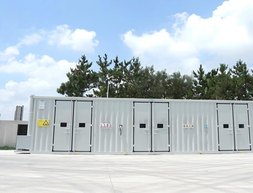
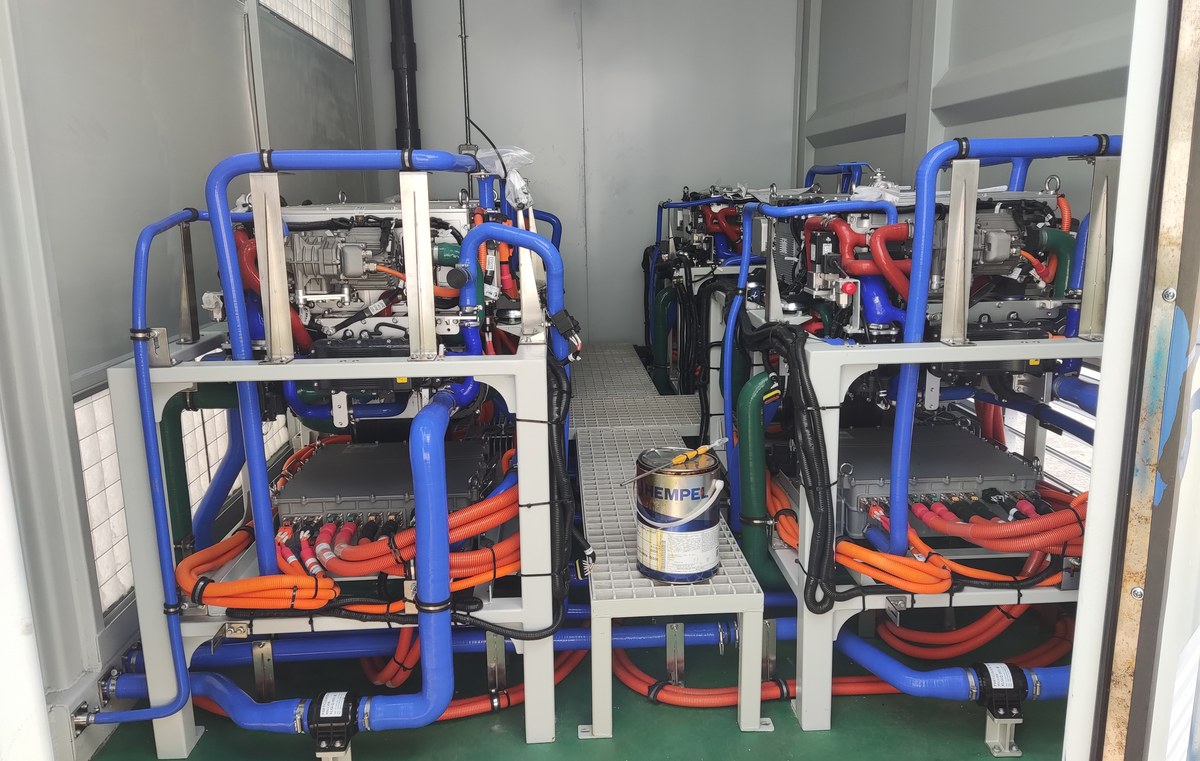
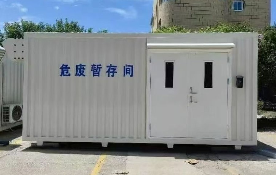
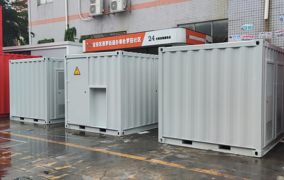
Some images are scheme illustrations and renders showing structure and layout. Final delivery follows the contract drawings.
What customers ask most
Do you design the water process?
We design filtration and dosing plants ourselves and work with your water engineer on RO and specialist processes. We will not pretend to be the process authority on a difficult water.
Can the chemical store be in the same box?
Only with a separate compartment, separate ventilation and bunding. On a 40 ft shell we build two rooms; on a 20 ft we put the store outside.
What happens in winter?
Trace heating and insulation on the pipework, and a drain-down procedure in the O&M file. A container does not freeze-proof itself.
Is it tested before shipment?
Wet tested in the yard with real water, and the test sheet travels with the unit. Membranes are preserved and the preservation record is in the file.
Can we add capacity later?
On a 40 ft shell, usually yes — spare ways and space for one more vessel. On a 20 ft, usually not, and we will say so at quotation.
Ask for a scheme for your site
Send the capacity, rack count, site conditions and local climate. You get a layout, a single-line diagram and a price, at no charge, revised until it works.